
Affiliate Disclosure: This article contains affiliate links. If you make a purchase through these links, we may earn a commission at no additional cost to you.
 メナ
メナHi, I’m Mena (@menachite), a hybrid mechanical/electrical engineer.
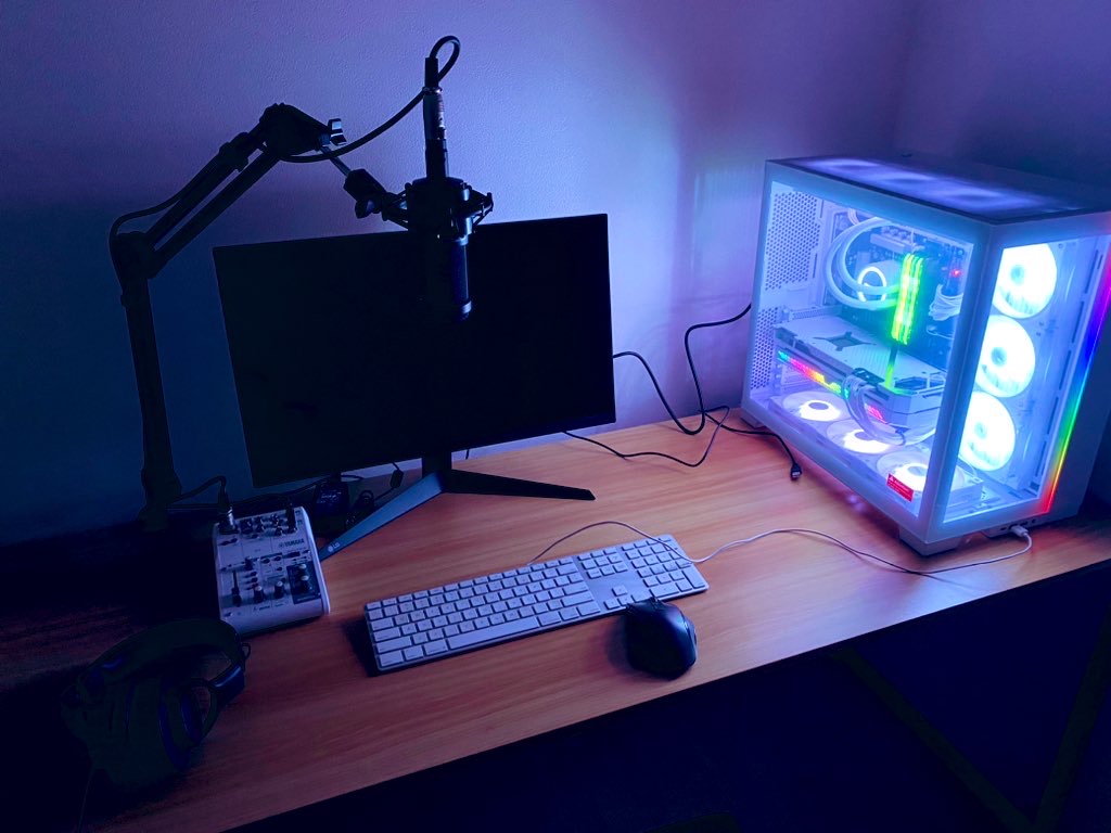
I recently bought a new high-end PC. Beautiful machine.
I don’t work remotely, but I wanted a serious rig to finally try some heavier projects. There was just one problem.
My home Wi-Fi is painfully slow.
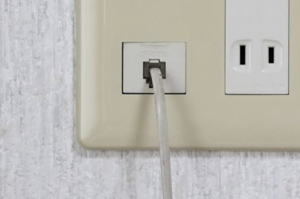
So I decided to run a wired Ethernet connection. Except my house doesn’t have a single wall-mounted LAN port anywhere — I bought it used, and there are no wiring diagrams either.
A contractor quote for adding just one port came back at roughly $150 — way too much for one jack. So I decided to DIY it myself. This is the story of how I added wall LAN ports to my house on a budget.
Step 1: The Shopping List
First I mapped out the house. Wiring mostly runs through the attic, drops down inside the walls, and terminates near outlets. I planned to run cable from the attic down to two rooms on the far side of the house from the router (roughly 10m each), so I bought a 30m cable and cut it into two runs — plus scrap for a couple of short patch cables.
Amazon turned out to be by far the cheapest way to source everything.
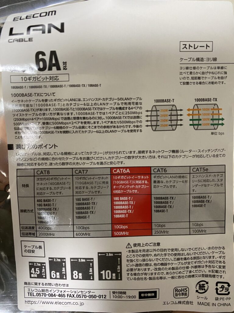
While picking a cable I learned there are different Ethernet categories — Cat5e, Cat6, Cat6A. Cat6A is newer and about 10x the throughput of Cat6, so when in doubt, I went with the faster spec.
The wall jack itself needs a termination tool to punch the wires down, so I bought a bundle that includes one, plus a spare jack module.
For the cover plate over the finished jack, use whatever single-gang keystone wall plate matches your local electrical standard — plate and box dimensions vary a lot country to country, so buy locally rather than importing one.
Step 2: Drilling the Mounting Holes
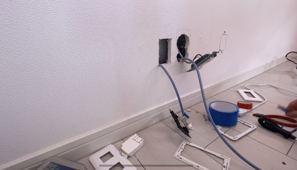
Drill the hole for the jack as close to an existing outlet as possible — if there’s conduit already running to that outlet, you can often fish the cable through it and save yourself a lot of grief (I did not get this lucky, more on that below). Check the attic first for existing conduit runs before you commit to a hole location.
For the hole itself, it’s either a hole-saw drill bit or a jigsaw. I went with the jigsaw since mistakes are easier to correct.
If you don’t already own a drill and a jigsaw, buy both — between the two you can handle almost any DIY project.
My walls were drywall, so it cut easily — a hand saw would probably have worked too.
Wiring the Jack
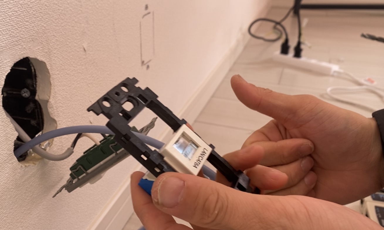
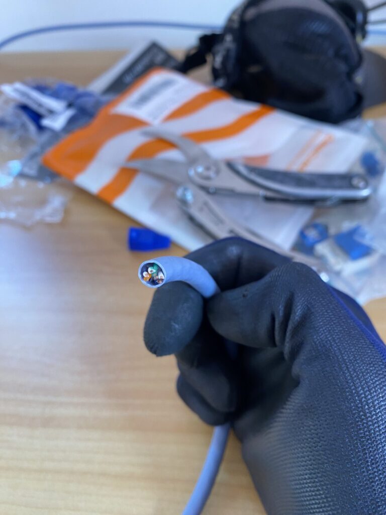
The termination kit’s jack module is designed to work either way up, which is a little confusing at first, but the wiring diagram printed on the connector keeps you on track. My cable happened to be “Type B” wiring, so I followed the manufacturer’s Type B diagram — if you’re not sure which type your cable is, the maker’s official site usually has a wiring PDF. Once the wires are seated, trim, snap the included jig into place until it clicks, and you’re done.
Routing the Cable to the Router Side
With the hole cut, I tried to route the cable down toward a nearby outlet — except the outlet’s wiring wasn’t in conduit at all, just bare cable straight through the wall. No way to fish anything through that.
So, plan B: access from the attic. Every house has a maintenance hatch somewhere in the ceiling — find it, set up a stepladder, and climb in.
It’s pitch dark up there even in daytime, so a headlamp is essential, and a proper ladder makes the climb much less sketchy.
Once up there, the walls were absolutely packed with insulation — I couldn’t even see where the outlet’s cable ran. Dangling a wire down blindly wasn’t going to work; I needed to actually see inside the wall cavity.
Enter the Endoscope Camera — and a Plot Twist
I picked up an affordable WiFi endoscope camera to scope out the wall cavity before committing to anything else.
Picture quality was better than expected — sharp enough to read the print on the cable jacket — with a built-in light for dark spaces. It struggled a bit at longer distances, but for peering inside a wall it was more than good enough.
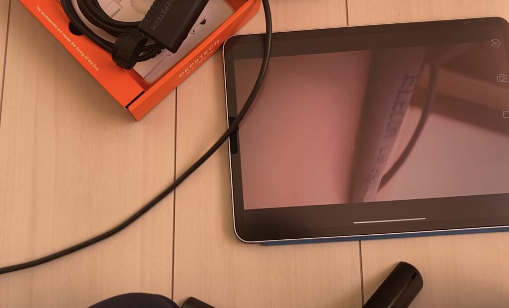
And that’s when I found out something important: the hole I’d already cut was directly below a window, and studs on both sides turned it into a dead end. That hole was unusable — I’d cut it for nothing.
Time for plan C. I tapped along the wall listening for the dull thud of a stud versus the hollow sound of open cavity, found a clear path, and cut a second hole. (The first hole got turned into a spare outlet opening and capped for now.)
Getting the cable through insulation-packed cavities turned out to work best by feeding a stiff, rigid tape measure down from the attic between the insulation and the wall, then pulling the cable up along it once the tape found the opening.
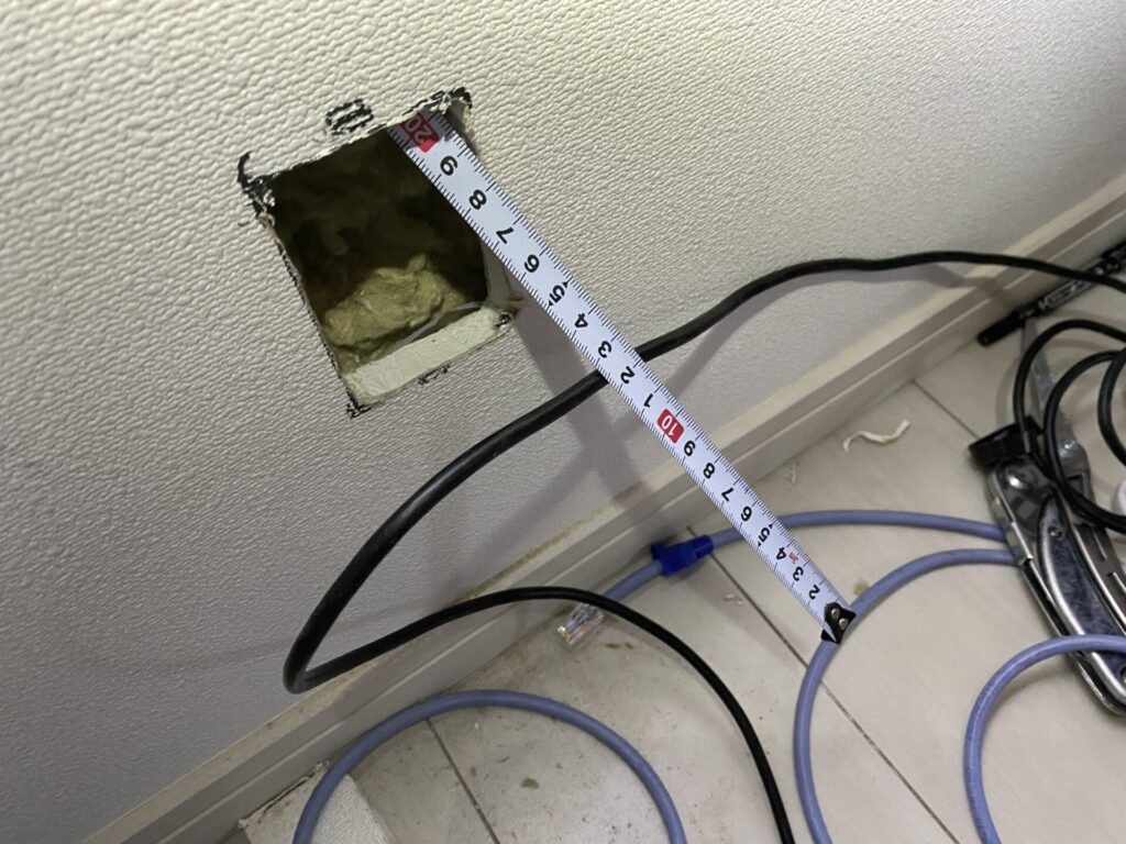
Feeding the tape through was its own workout — I used the endoscope again to confirm the tape’s position along the way.
A Word of Caution About Fiberglass Insulation
The attic was packed with fiberglass batting. It looks soft, but the fibers are surprisingly sharp and go straight through clothing into skin — I ended up with an irritated, itchy arm after reaching in bare-armed to fish the cable through. After that I wrapped my arms in tape and wore rubber gloves. Fiberglass insulation isn’t toxic, but the irritation (likely combined with trapped dust) is no fun — protect your skin if your attic has it.
Finishing the Router-Side Wiring
With the cable finally through, terminate it into the jack the same way as before, then screw the cover plate to the wall. Use a countersunk wood screw sized for your plate’s mounting holes — mine needed 4 screw points instead of the usual 2 since drywall alone doesn’t hold a plate very rigidly otherwise.
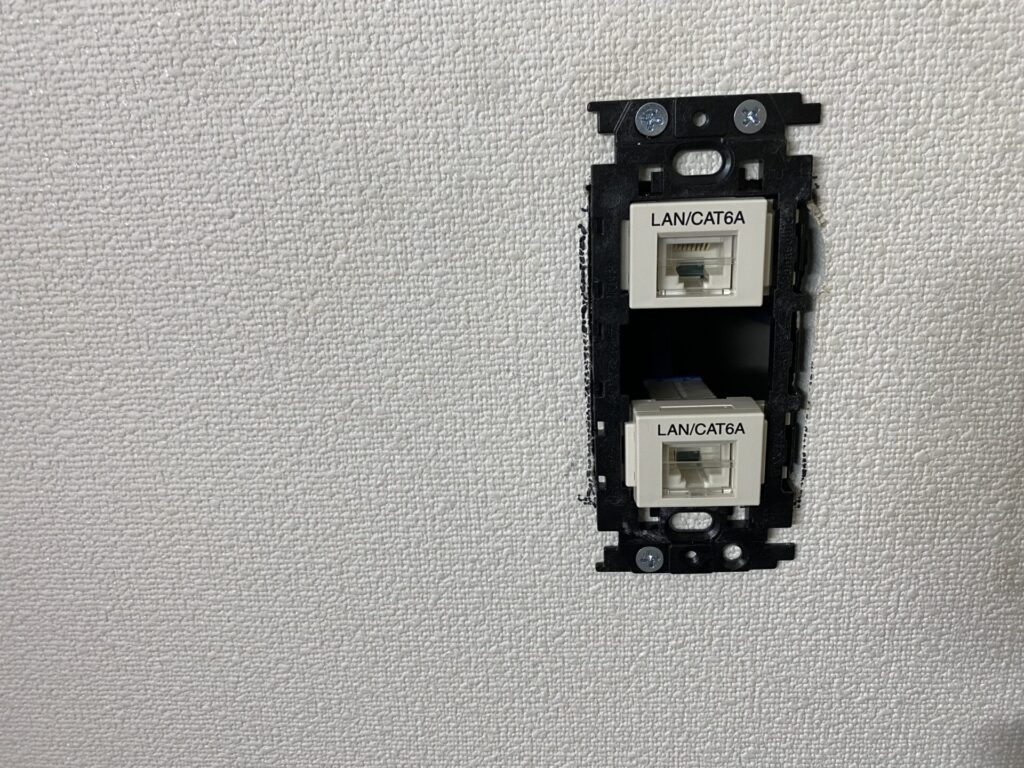
Once the cover is on, it genuinely looks like a professional installation — a nice reminder of how well-engineered these off-the-shelf parts really are.
Making the Patch Cables from Leftover Wire
With cabling done, I used the scrap from the 30m spool to make a couple of short patch cables — router-to-jack and jack-to-PC. A basic all-in-one crimping kit (crimper, stripper, connectors, a case) is the easiest way to get started.


Strip the jacket, straighten and order the eight wires exactly per the standard (from left, pins face down: white/orange, orange, white/green, blue, white/blue, green, white/brown, brown), seat them fully into a connector, then crimp — the trickiest step is getting all eight wires seated evenly before you crimp. I fumbled it twice before it held.
Testing for Wiring Mistakes


A cheap cable tester is worth every penny here — a mis-wired cable can damage connected equipment, so don’t skip this step. Plug your finished cable in, and the tester lights up pins 1 through 8 in sequence on both ends; any mismatch means a wiring error. You can even test each wall jack independently this way, checking both ends from a distance.
Time and Cost Breakdown
Total time: about 4 days, done in spare moments around a young kid at home — materials day, cable-running day, a day fixing my mistakes, and a finishing/testing day. With a clear weekend and no rework needed, I’d estimate 2 days. Materials ran about $95, tools about $170 (though I already owned most of the tools, so my out-of-pocket cost was closer to $95 + a little).
Did Cat6A Actually Speed Things Up? The Results
Before the wiring project my only option was a flaky Wi-Fi dongle pulling well under 10Mbps — genuinely miserable. Cat6A is rated for up to 10Gbps.
I ran a speed test after everything was hooked up. Result: 746Mbps down, 631Mbps up. Perfectly fine for daily use — but I was hoping to clear 1Gbps, and it didn’t happen. Time to investigate why.
First suspect: the motherboard’s onboard Ethernet controller. Checking the spec sheet on a board like this one, the integrated Gigabit Ethernet controller tops out at 1Gbps — plausible, but I wasn’t hitting even that, so it wasn’t the main bottleneck.
The real culprit turned out to be the router. My existing Wi-Fi 6 router advertises fast wireless speeds, but checking the spec sheet, its wired LAN ports are Gigabit-only — capped at 1Gbps regardless of how fast the Wi-Fi radio is. I’d assumed “Wi-Fi 6” implied fast wired ports too. Nope. That was the bottleneck the whole time.
Routers with a genuine multi-gig wired port are still fairly rare and pricier — something like a router with a dedicated 2.5G port is the next logical upgrade whenever the budget allows. For now it’s a bit over budget, so that one’s on the wishlist.
Wrap-Up
Getting real multi-gig speeds at home clearly costs real money once you add up the router, the motherboard NIC, and the cabling. Between materials and tools, I was in this for a bit under $300 total — cheaper than paying a contractor for one single jack, with tools left over for the next project. Given all the failed holes, insulation scratches, and endoscope detours, it was still a solidly worthwhile weekend project. Hope this helps if you’re considering the same thing.